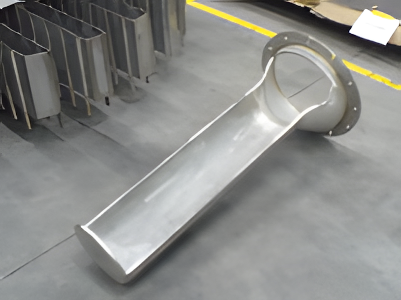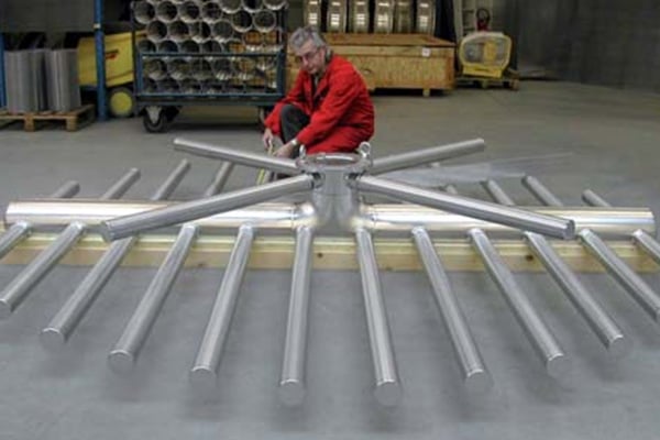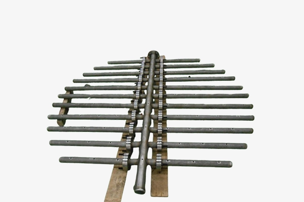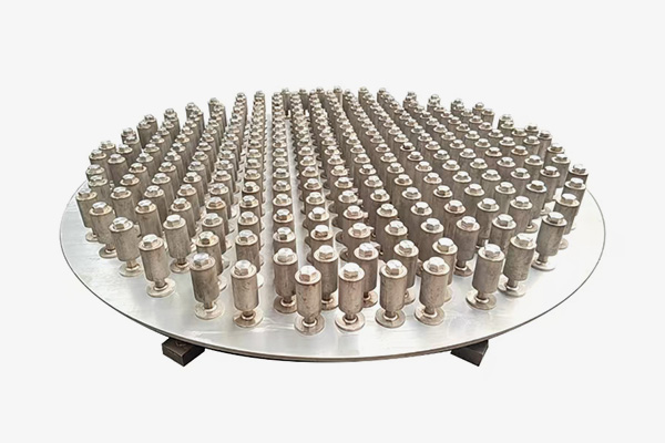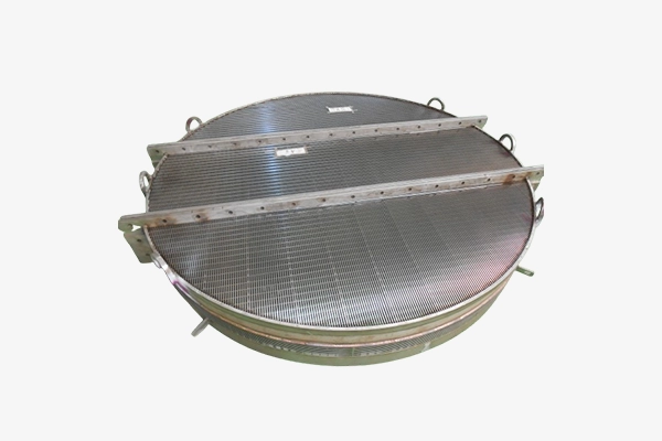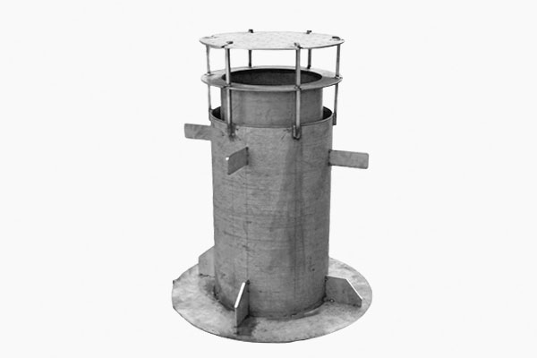
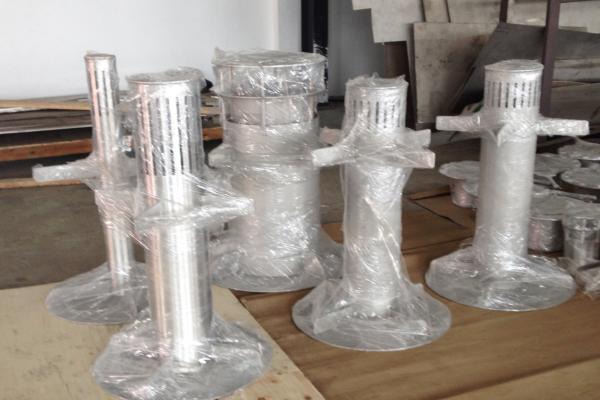
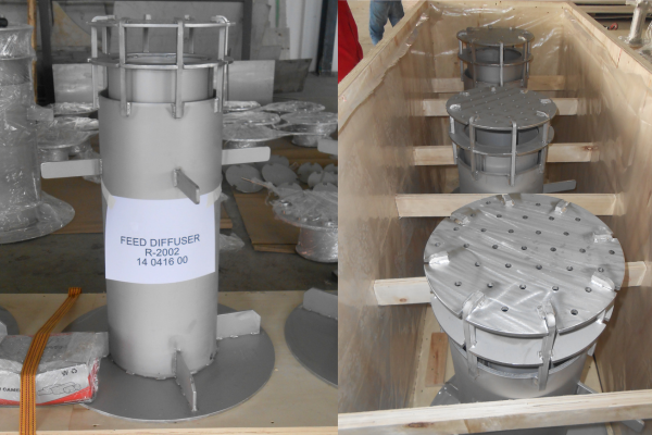
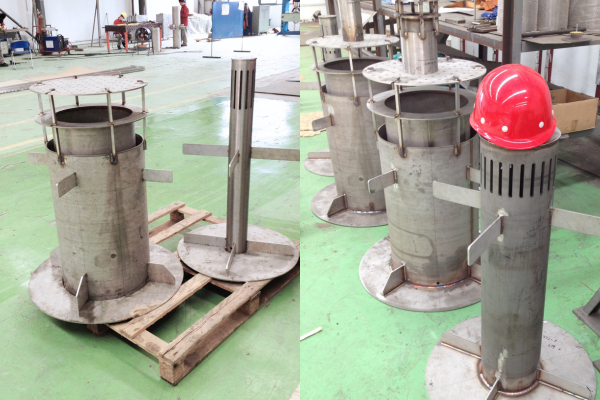
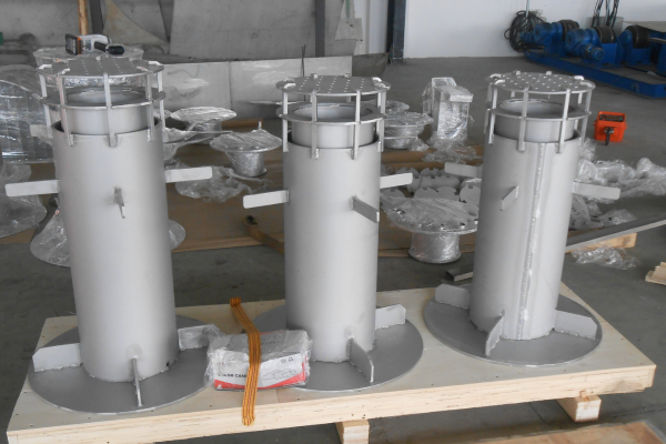
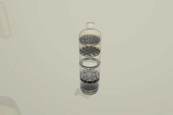
Feed Diffuser
Feed diffuser is diverting the incoming flow from the inlet nozzle towards the reactor.
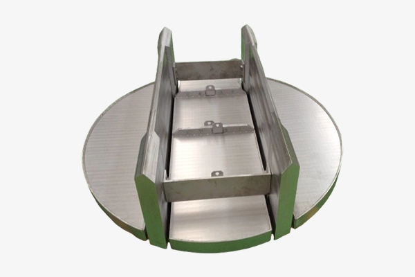
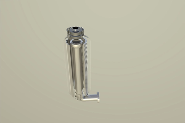
- The 3D design of the feed diffuser ensures a perfect fit with the pressure vessel nozzle and inlet pipe flange interface.
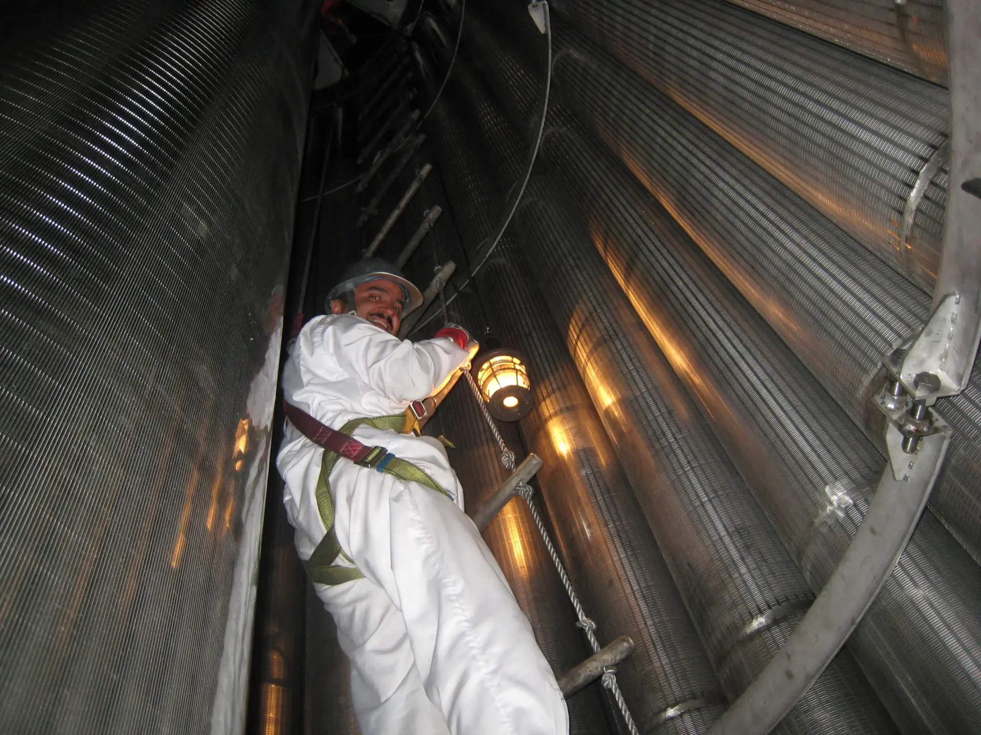
- Design includes holding and handling features to facilitate easy installation in tight nozzle spaces.
- Welding procedures are designed to monitor weld strength and enhance operational durability.
Application: Gas sweetening, gas drying, sulphur removal, hydrotreating, hydrocracking, hydrogenation, etc.
Design based on your application
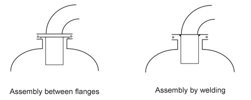
In a downflow system, the inlet nozzle doubles as a manway for inserting internals and loading catalysts. The connecting pipe typically has a smaller diameter with a 90° elbow, enabling easy assembly and disassembly. The pipe is welded to a custom reduction flange, and the feed diffuser can be attached either to this flange or placed in a groove between flanges.
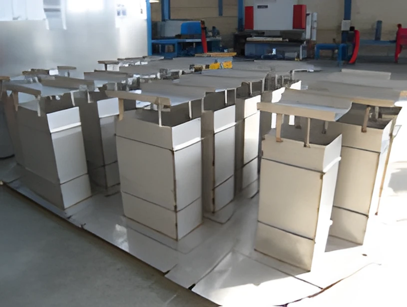
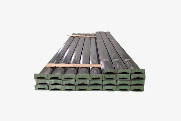
The feed diffuser is designed using a combination of plates, screens, and perforated plates, based on the flow dynamics of the reactor’s top head and process requirements. An impingement plate is positioned to face the incoming flow, diverting it through multiple channels. Its dimensions depend on the diameter of the inlet pipe and the nozzle height.
Design Parameters
Process parameters:
The reactor’s internal length, number of channels, and impingement plate design are determined by process hydrodynamics, including flow rate, gas-liquid distribution, and allowable pressure drop.
Mechanical parameters:
Both static and dynamic loads are essential factors in determining the required reinforcement.
Faq
{acf_faq_list_faq-txt}
We support you 24/7
Our expertise is here to serve you
We take every question and need of yours seriously. Feel free to contact us!
Over 20 years of experience in welding special alloys
100% RT&full material traceability
Integrated delivery from simulation to FAT