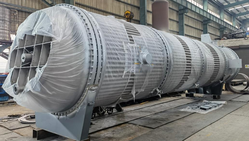
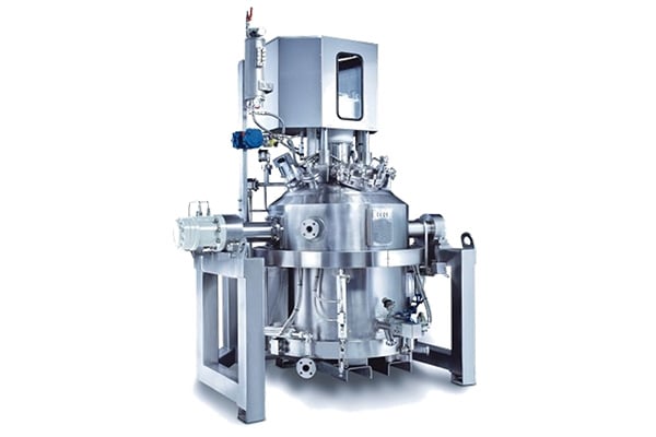
Agitated Nutsche Filter Dryer
Main Features:
1. One piece of process equipment can replace traditional crystallization kettles, centrifuges, scrubbers and dryers;
2. High efficiency, energy saving, safety and environmental protection;
3. Widely used in the chemical, pharmaceutical, food and other industries;
4. Completely enclosed operation, suitable for aseptic working conditions;
5. Dual certification (GMP FDA) possible.
Main Configuration:
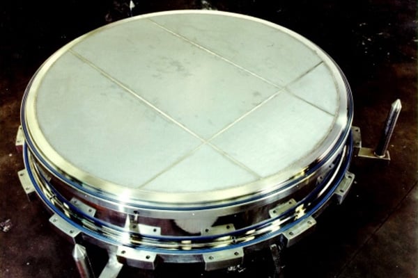
- Canister Filters, Flat Sintered Mesh or PTFE Cloth Filters;
- The hydraulic system assists the stirring shaft to move up and down, open and close the filter chassis, and raise and lower the filter chassis;
- The control system completes the filtering, washing and drying processes;
- Auxiliary facilities: complete unloading, online sampling, online washing, vacuum drying, etc.
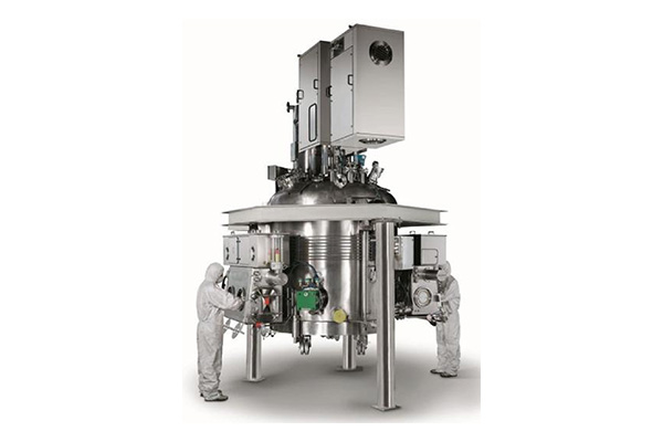
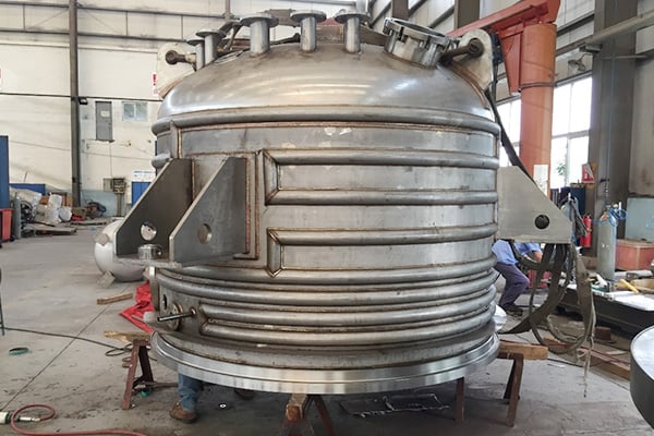
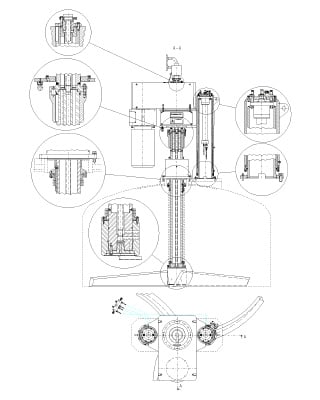
Core Structure
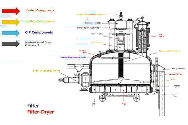
Core Components
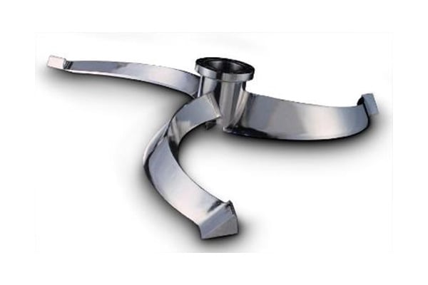
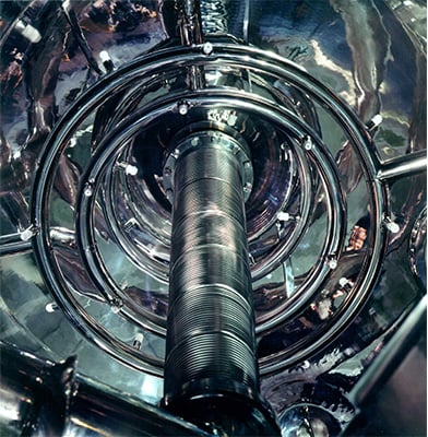
1 Heated Components
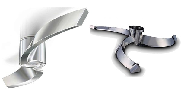
Heated Stirring Shaft
Each stirring blade is internally designed with a heating/cooling circuit that extends to the tip of the blade; this design creates turbulence within the blade, enhancing heat transfer efficiency;
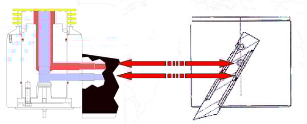
When the material comes into contact with the bottom edge of the blade, it “rolls over” the blade due to its sloped surface, thereby optimizing heat transfer.
2 Sealing Components
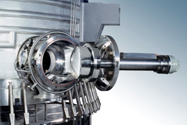
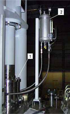
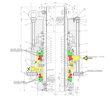
Spindle Mechanical Seal System:
Case Study:
The seal between the spindle and the tank (accommodating both rotational and axial movement) is achieved using the double-face mechanical seal (1) shown in the figure. This mechanical seal is available in either a “dry” or “wet” configuration, with the primary difference being the lubrication medium. The corresponding lubrication system (2) is fully configured accordingly (thermosiphon principle + motor-driven – wet type).
Based on differences in lubrication media and sealing configurations, the main types of mechanical seals include:
single-face mechanical seals, double-face wet mechanical seals, double-face dry contact mechanical seals, double-face dry non-contact mechanical seals, and double-face single-end non-contact mechanical seals.
3 CIP Components
Filter Cake Displacement Cleaning System
Tank Cleaning System
Tank Top Cleaning System
Mechanical Seal Cleaning System
Metal Bellows Cleaning System
Side-Mounted Discharge Valve Cleaning System
“Air Knife” Cleaning System
Piping Self-Cleaning System
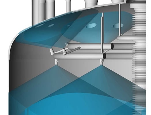
Online washing and cleaning are performed using spray nozzles.
The arrangement of the spray nozzles ensures that all surfaces are thoroughly cleaned.
Ensure that all surfaces in contact with the product are thoroughly cleaned.
A riboflavin test will be conducted after the equipment has been cleaned.
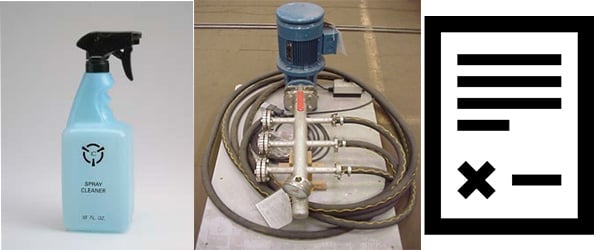
Spray the riboflavin solution onto the inner surfaces of the equipment using a spray bottle.
Adding a starch-based additive increases the viscosity of the riboflavin, effectively causing it to adhere to the inner surfaces of the equipment.
Clean the inner walls of the equipment using an in-line cleaning system.
Inspect the inner surfaces of the equipment with ultraviolet light; any residual riboflavin will emit a bright green fluorescence.
Issue a final inspection report and designate non-validated areas.
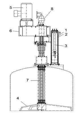
4 Mechanical and Drive Components
Drive Assembly
Spindle Up/Down
The entire drive assembly is supported by the drive assembly bracket (1). The hydraulic cylinder (3), which performs the up/down motion guided by the chrome-plated guide rod (2), is housed inside the guide rod (2). The “hydraulic down” motion has both fast and slow speeds; the ‘slow’ speed can be preset via the hydraulic control panel. The “compression force” (4) exerted by the stirring shaft on the filter cake can also be preset on the hydraulic control panel; the drive unit’s lifting/lowering stroke can be mechanically limited (min., max.).
Main Shaft Agitation
The drive is powered by a motor (5), which transmits power through a reducer (6) to the main shaft (7), thereby driving the heated stirring shaft (4). The top of the stirring shaft is sealed via a rotary joint. For the entire unit, two motors are required: the main motor (5) and one
Faq
{acf_faq_list_faq-txt}
We support you 24/7
Our expertise is here to serve you
We take every question and need of yours seriously. Feel free to contact us!
Over 20 years of experience in welding special alloys
100% RT&full material traceability
Integrated delivery from simulation to FAT
.png)