Jacket, Agitation and Insulation: The Three Key Components of a Pressure Vessel
Перейти к разделу
1. What Does Each Component Do?
The three components divide the work as follows: the jacket controls temperature through the shell wall, agitation controls the flow field inside the vessel, and insulation controls the boundary with the environment. No one of them can be judged in isolation.
| Component | Core function | Acts on | Key performance indicators |
|---|---|---|---|
| Jacket | Heating / cooling — temperature control | Vessel contents, through the shell wall | Heat-transfer coefficient (typically 300–1,200 W/(m²·K) for steam, 500–1,500 for water), heat-transfer area, pressure rating (≤ 6.4 MPa for half-pipe) |
| Agitation | Mixing, mass transfer, heat-transfer enhancement | Flow field inside the vessel | Mixing time (typically 30–120 s for turbulent low-viscosity duty), circulation flow, shear-to-pumping ratio, power per unit volume (0.1–1 kW/m³ typical) |
| Insulation | Thermal isolation | Vessel-to-environment boundary | Thermal conductivity λ (0.024–0.040 W/(m·K) at 25 °C), insulation thickness, surface heat loss |
The three are coupled, not independent. Two couplings matter most:
- Agitation feeds the jacket. Most of the in-vessel resistance to heat transfer sits in the stagnant film at the wall. Stronger agitation thins that film and raises the jacket-side coefficient — the same jacket area then passes a larger heat flux.
- Insulation sets the jacket’s workload. The lower the heat loss, the less heat the jacket has to make up, and the smaller the heating system can be. Cutting surface heat loss from 200 W/m² to 80 W/m² directly reduces required steam consumption by a proportional margin.
2. How Does a Jacket Work?
A jacket is a closed annular cavity built onto the outside of the shell. It is not connected to the vessel interior — a separate service medium circulates through it and transfers heat across the shell wall by conduction.
The operating sequence has four steps:
- Service medium admitted — Steam, thermal oil or cooling water enters the jacket cavity.
- Transfer across the wall — Heat passes through the shell wall; the two streams never contact.
- Contents heated or cooled — The batch follows the process temperature profile.
- Medium returns to the loop — Spent medium leaves the jacket and returns to the utility system.
Which heat-transfer medium should I use?
| Medium | Temperature band | Film coefficient | Use when |
|---|---|---|---|
| Steam | Saturated, typically 100–180 °C at 0.1–1.0 MPa | 5,000–15,000 W/(m²·K) — highest of the three, because condensation releases latent heat | Standard heating duty; the default choice |
| Thermal oil | Up to 350 °C | 500–2,000 W/(m²·K) | Higher temperatures than steam allows, or where smooth stable control is required |
| Cooling water | Ambient to ~30 °C | 1,000–4,000 W/(m²·K) | Heat removal and cool-down; controlling exothermic reactions |
Design note. Steam gives the highest film coefficient by a wide margin, which is why it dominates heating duty. Its weakness is a temperature ceiling and the fact that it cannot be throttled smoothly — for tight isothermal control at high temperature, thermal oil usually wins despite the lower coefficient.
Because a jacket works by indirect heat transfer, the service medium never touches the process material. That is precisely why it is standard in pharmaceuticals, food and other industries with stringent cleanliness requirements.
3. What Are the Four Jacket Types?
Classified by how the cavity is constructed, there are four main types. The decisive variable is jacket-side design pressure.
| Тип | Structural character | Main advantage | Pressure capability | Typical application |
|---|---|---|---|---|
| Conventional / full jacket | Complete outer shell forming a continuous annular cavity | Simple structure, easy fabrication, large heat-transfer area | Low — typically ≤ 0.6 MPa | General heating and cooling where pressure is low and shell demands are light |
| Structural-steel jacket | Flow channels formed by welding structural sections (angle steel, flat bar) to the shell | High rigidity; reinforces the shell | Medium — typically ≤ 2.5 MPa | Higher jacket-side pressures where the shell also needs strengthening |
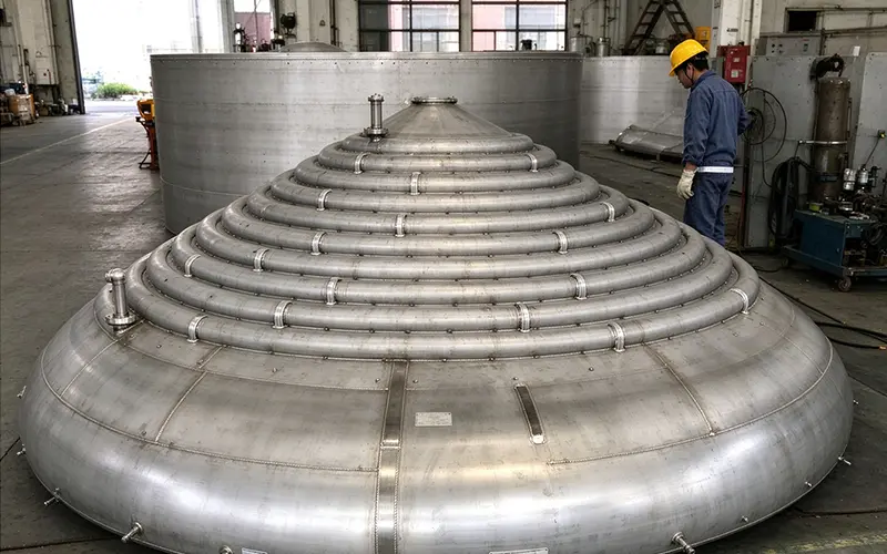
| Half-pipe jacket | Half pipes (or semi-circular sections) wound and welded onto the outer wall | Easy to fabricate, favourable shell loading, less material consumed | Up to 6.4 MPa per HG/T 20569 | Medium and large vessels at high jacket-side pressure where shell thickness must be kept down |
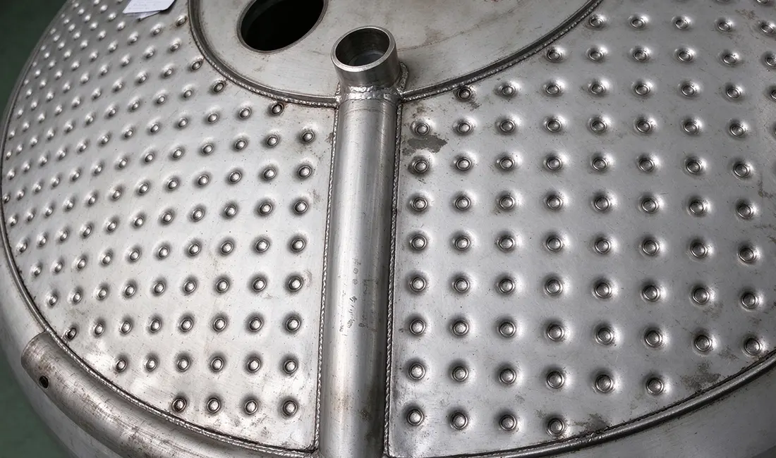
| Dimple jacket | Array of dimple-shaped weld points formed into the cavity | Enhances heat transfer while raising pressure capability and rigidity | Medium–high, typically ≤ 4 MPa | Duty requiring both high heat-transfer efficiency and high jacket-side pressure |
Quick decision lines:
- Low pressure, simple, economical → conventional jacket
- High pressure + shell reinforcement → structural-steel / half-pipe
- High pressure + high heat-transfer efficiency → dimple jacket
The dimple jacket’s array of weld points does two jobs at once: it shortens the unsupported span (structural strengthening) while continuously disturbing the flow (heat-transfer enhancement). A single geometric feature delivering both is why it commands a price premium.
Where the numbers come from. Pressure-capability figures follow HG/T 20569 Stirred Vessels and GB/T 151 Heat Exchangers; vessel design and pressure testing follow GB/T 150 and, for export projects, ASME BPVC Section VIII Division 1. Project specifications can and do set tighter limits — always design to the governing code of the installation.
4. How Does Agitation Work?
An agitation assembly is a power–transmission–execution chain: motor → gear reducer → agitator shaft → impeller.
| Element | Функция | Why it matters |
|---|---|---|
| Motor | Supplies driving power | Sized on power per unit volume, typically 0.1–1 kW/m³ for general duty; high-shear dispersion can reach 2–5 kW/m³ |
| Gear reducer | Steps down to low speed, high torque | Output speed typically 30–300 rpm for low-viscosity duty, 5–60 rpm for viscous duty |
| Agitator shaft | Transmits torque through the head | Requires a seal — the point where leakage and fugitive emissions originate |
| Impeller | Acts on the fluid; sets the flow-field shape | The single most consequential selection decision |
How the flow field forms
- Mechanical energy is transferred. The rotating impeller passes energy into the fluid. A highly turbulent zone forms close to the impeller — where mixing, dispersion and reaction are most vigorous.
- A high-velocity jet is produced. Fluid discharged by the blades drives circulation around the vessel.
- Bulk circulation follows. The jet entrains surrounding fluid into a loop covering the whole vessel, eliminating temperature and concentration gradients.
Why agitation changes your heat-transfer coefficient
This is the coupling engineers most often under-price. The in-vessel film coefficient scales approximately with impeller speed to the power of about 0.6–0.7 in the turbulent regime. In practice:
- Doubling impeller speed raises the vessel-side coefficient by roughly 50–60%.
- A highly viscous batch that cannot be made turbulent may show a vessel-side coefficient 5–10× lower than the same vessel running a low-viscosity batch — which is exactly why viscous batches heat slowly.
This is why specifying a bigger jacket to fix a slow heating problem often fails: the bottleneck is the wall film, not the jacket area.
5. Impeller Selection by Viscosity
Selection reduces to matching material viscosity against the required flow pattern (radial versus axial). Viscosity sets the impeller diameter and speed; the objective sets the flow pattern.
Viscosity bands and recommended impellers
| Viscosity band | Recommended impeller | D/T ratio | Speed range | Flow pattern |
|---|---|---|---|---|
| < 50 cP (water-like) | Paddle or turbine | 0.3–0.5 | 100–300 rpm | Radial with some axial |
| 50–10,000 cP | Turbine (flat or pitched blade) | 0.3–0.5 | 50–150 rpm | Strong radial |
| 10,000–50,000 cP | Anchor or large paddle | 0.9–0.95 | 20–60 rpm | Radial with wall sweeping |
| > 50,000 cP (paste-like) | Helical ribbon | 0.9–0.95 | 5–40 rpm | Strong axial, bulk plug flow |
Impeller types compared
| Impeller | Structural character | Dominant flow | Best suited to |
|---|---|---|---|
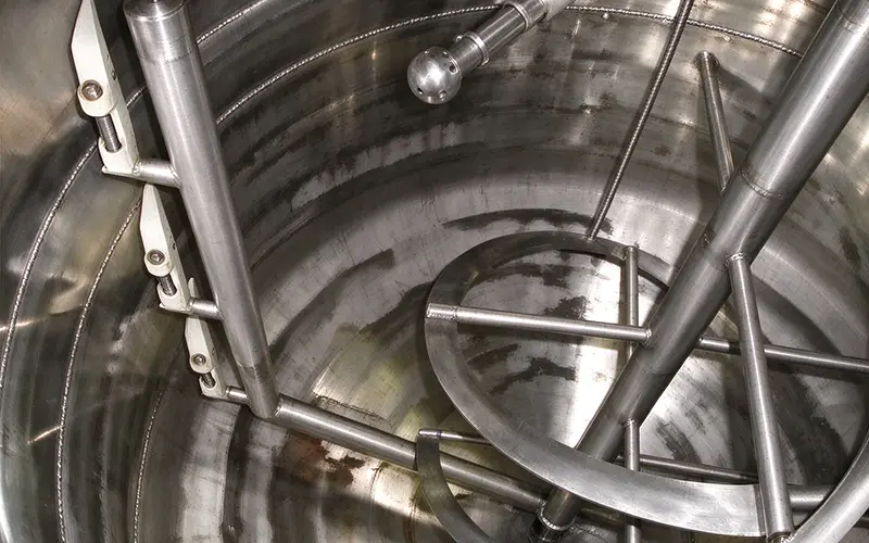
| Anchor | Blade outline follows and nearly touches the vessel wall | Mainly radial, with a wall-sweeping action | High-viscosity materials; running close to the wall continually renews the film there and improves heat transfer |
| Paddle | Simple flat blades | Radial with some axial component | General mixing, dissolution and heat transfer in low-viscosity liquids |
| Turbine | Multi-blade disc turbine; high shear capability | Strong radial | Gas–liquid dispersion, liquid–liquid extraction, solids suspension — any duty needing high shear |
| Helical ribbon | Helical ribbon, diameter close to the vessel diameter | Strong axial circulation, bulk plug flow | Very high viscosity; duty needing top-to-bottom circulation with no dead zones |
Two selection rules. (1) Viscosity sets impeller diameter — low viscosity → small diameter, high speed; high viscosity → large diameter, low speed. (2) Objective sets flow pattern — bulk homogenisation → strong axial circulation; dispersion, emulsification, dissolution → high-shear turbine.
The most common specification error is choosing an impeller for mixing performance alone and ignoring its effect on heat transfer. In a jacketed reactor, the impeller is also a heat-transfer device. Where heating or cooling is the bottleneck, an anchor or helical ribbon running close to the wall will often outperform a theoretically “better mixer”.
6. What Materials Are Used for Vessel Insulation?
Insulation is one of the core applications of thermal isolation. It does not alter the process — but it directly shapes the process energy balance.
The composite sandwich structure
| Layer | Функция | Typical material |
|---|---|---|
| ① Insulation layer (core) | Blocks heat flow using low-conductivity material | Rock wool, aluminium silicate fibre, polyurethane foam |
| ② Vapour barrier (where required) | Stops water vapour ingress so the insulation cannot become wet | Polyethylene film |
| ③ Protective cladding (outer) | Waterproofing and corrosion protection | Colour-coated steel sheet, aluminium sheet, glass-reinforced plastic |
None of the three layers is dispensable. The insulation layer makes it work; the cladding makes it last. Insulation without effective cladding admits rainwater, and once the material absorbs water its thermal conductivity climbs sharply and performance decays fast — the most common mode of insulation failure in the field.
Insulation materials compared
| Материал | Category | Thermal conductivity λ | Max service temp | Typical use |
|---|---|---|---|---|
| Rock wool | Inorganic fibre | 0.040 W/(m·K) @ 25 °C; 0.055–0.070 @ 200 °C | ~650 °C | General-purpose insulation on medium- and high-temperature equipment and piping |
| Aluminium silicate fibre | Inorganic fibre | 0.038–0.045 W/(m·K) @ 25 °C | ~1,000 °C | Preferred for high-temperature vessels |
| Polyurethane foam | Organic foam | 0.024 W/(m·K) @ 25 °C — lowest of the three | ~120 °C | Low-temperature and cold-service duty; closed-cell structure also addresses condensation |
Reading the table correctly matters more than the numbers themselves. Aluminium silicate fibre and rock wool have similar λ at ambient, but their performance diverges sharply as temperature rises — organic materials age and carbonate, which is why polyurethane foam is unsuitable above roughly 120 °C regardless of its superior ambient λ.
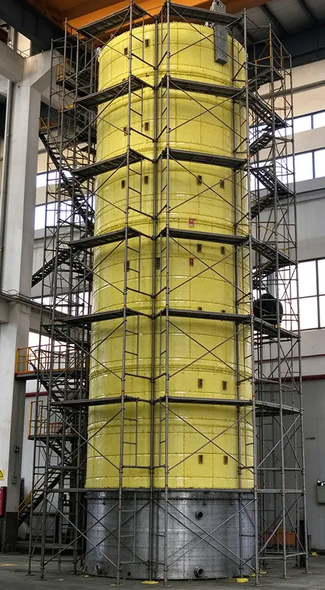
7. Insulation Design: Four Rules and the Thickness Question
The four design rules
- Select against the service conditions. Material and construction must follow from operating temperature, character of the medium, and service environment together.
- Inorganic fibre first for high temperature. High-temperature vessels should preferentially use aluminium silicate fibre, to avoid ageing and carbonisation of organic materials at temperature.
- Keep condensation in mind at low temperature. Low-temperature vessels must address insulation and condensation together — blocking inward heat while also preventing the outer surface falling below the dew point, which causes sweating, frosting and cladding corrosion.
- Thickness comes from thermal calculation, not rule of thumb.
How thick should insulation be?
Insulation thickness is a two-sided constraint — thicker is not automatically better:
| Direction | Consequence |
|---|---|
| Too thin | Excessive heat loss, higher energy consumption, and possibly a surface temperature above 60 °C — a burn hazard under GB/T 4272 and general safety practice |
| Too thick | Extra weight on supports, larger cladding dimensions, and diminishing marginal energy saving |
Practice is to take the economic thickness — the thickness at which the sum of annual heat-loss cost and annualised capital cost is minimised. For typical steam equipment at 150–250 °C in a temperate climate, this usually lands between 50 mm and 150 mm, with larger pipe or vessel diameters pushing toward the upper end and higher energy prices favouring thicker insulation. Worked example: insulating a bare 200 °C surface down to a 40 °C surface temperature cuts heat loss from roughly 1,200 W/m² to under 100 W/m² — an order-of-magnitude reduction that repays the material cost within about two years at typical industrial energy prices.
Applications
| Сервис | Objective | What to watch |
|---|---|---|
| High temperature (steam storage tanks, high-temperature reactors) | Hold a stable medium temperature; reduce the heating system’s makeup load | Steadier reaction temperature also reduces product variation from temperature swings |
| Low temperature (cryogenic liquid nitrogen tanks) | Block external heat from entering | Must be paired with a vapour barrier and condensation control; prevents vaporisation losses and over-pressure risk |
Typical insulated items: steam storage tanks, reactors, transfer piping, cryogenic liquid nitrogen tanks, heat-exchange equipment.
8. How Do Jacket, Agitation and Insulation Work Together?
On a single jacketed reactor, the three form a closed supply-and-retain energy chain, coupled at every step:
The energy chain closed loop
- The jacket supplies heat. Steam enters the jacket cavity and releases heat through the shell wall, bringing the batch to reaction temperature.
- Agitation homogenises it. The impeller carries heat rapidly through the vessel, removing the difference between wall region and centre.
- Agitation feeds back into heat transfer. Turbulence thins the wall film and raises the jacket-side coefficient, so the same area passes more heat flux.
- Insulation stops it leaking away. The insulation layer keeps gained heat inside, cutting the steam consumption and heating capacity needed to hold temperature.
- Back to the jacket. With required heat input down, jacket sizing and utility provision can be optimised in turn — the loop improves itself.
There is an order in which these should be optimised: get heat transfer and mixing right with agitation first, then bring losses down to a sensible level with insulation, and only then size the jacket area and medium. Doing it the other way round — enlarging the jacket before losses are under control — usually wastes capital.
In one sentence
The jacket decides whether heat can get in, agitation decides whether heat and material can spread, and insulation decides whether heat will escape. A shortfall in any one discounts the other two: however large the jacket and however vigorous the impeller, energy simply flows to the environment if the insulation has failed; and however good the insulation, the vessel will still stratify and react unevenly if agitation is inadequate.
9. FAQ
What is the difference between a jacket and a coil in a pressure vessel?
A jacket is an annular cavity built onto the outside of the shell, so it adds heat-transfer area without occupying internal volume. A coil sits inside the vessel and gives a higher overall coefficient but intrudes on the working volume and complicates cleaning. Jackets suit cleanliness-critical and large-area duty; coils suit high-flux duty in smaller vessels.
How do I choose between a half-pipe and a dimple jacket?
Half-pipe jackets reach the highest jacket-side pressure — up to about 6.4 MPa per HG/T 20569 — with favourable shell loading and lower material consumption. Dimple jackets typically cap around 4 MPa but deliver better heat transfer per unit area because the weld-point array continuously disturbs the flow. Choose half-pipe when pressure governs, dimple when heat-transfer efficiency governs.
Which impeller should I use for a high-viscosity batch?
Above roughly 50,000 cP, use a helical ribbon with a diameter ratio of 0.9–0.95 and a speed of 5–40 rpm; it produces strong axial circulation with no dead zones. Between 10,000 and 50,000 cP, an anchor or large paddle running close to the wall is usually the better choice, because wall-sweeping improves heat transfer as well as mixing.
How thick should vessel insulation be?
Insulation thickness must come from a heat-transfer calculation, not a rule of thumb. The correct target is the economic thickness — where annual heat-loss cost plus annualised capital cost is minimised. For typical steam equipment at 150–250 °C this usually lands between 50 mm and 150 mm, and the calculation must also keep surface temperature below 60 °C to avoid a burn hazard.
Why do viscous batches heat up so slowly?
Most of the in-vessel resistance to heat transfer sits in the stagnant film at the wall. Viscous batches cannot be driven turbulent, so that film stays thick and the vessel-side coefficient can be 5–10× lower than for a low-viscosity batch in the same vessel. Increasing jacket area does not fix it — improving wall renewal does.
Can insulation be added without a vapour barrier at low temperature?
No. At low temperature the outer surface can fall below the dew point, causing sweating, frosting and cladding corrosion. A vapour barrier is what stops water vapour reaching the insulation core; without it the material absorbs water, thermal conductivity climbs sharply, and performance decays within a season.
© Jacket, Agitation and Insulation: The Three Key Components of a Pressure Vessel
Хотите узнать больше о нашей продукции?
Посмотреть все товары сейчас English
  Spanish
  Russian